Pass One - Visibility Splatting
In this pass, each splat is rasterized for the purposes of filling the depth buffer only. In the next pass we blend those splats whose depths differ by some small constant. This allows us to blend neighboring splats, while maintaining visibility.Splats are rendered using custom vertex and fragment shaders. The splats enter the pipeline as points along with their other attributes. A vertex shader computes the size of the splat onscreen by projecting the eye-space extent of the splat onto the viewplane and setting the size s of the rectangular point to be rasterized. This causes each splat to be rasterized by the hardware into a size s x s rectangle in the framebuffer centered around the projected position of the splat.
Each fragment of the splat is then processed by a custom fragment shader. Since a conservative estimate of the size of the splat onscreen is computed by the vertex shader, the fragment shader first determines whether the fragment is in the interior of the splat by inverting the viewport transformation and back-projecting the fragment position into a ray which is intersected with the supporting plane of the splat. If the fragment is determined to be within the interior of the splat in eye-space, it is accepted, otherwise it is abandoned. For accepted fragments, a perspectively correct depth is computed and passed onto the frame buffer for depth testing.
Pass Two - Attribute Splatting
In this pass, the geometry is processed again using the depth buffer results from the previous pass. Vertex processing is exactly the same as in pass one, but there are some changes to the fragment processing. In order to only blend those splats which overlap locally on the surface, overlapping splats are blended only when their z values differ by some small constant. Each splat is then weighted with an alpha according to some reconstruction kernel, typically Gaussian, whose influence decreases radially with the distance from the center of the splat. The contributions of overlapping splats that pass the depth test are accumulated in the frame buffer.Using multiple rendering targets, it is possible to render not only blended material properties, but also blended normals as well. In the third pass, the normals and material properties can be combined to perform phong shading.
Pass Three - Shading
As a result of pass two, we now have the blended material properties and normals of the surface at each pixel in the rendered image. This information is sufficient for performing phong shading. However before shading calculations are performed the color and normal at each pixel must be normalized by dividing the color and normal by the accumulated weight at that pixel. This is required since the reconstruction kernels have been discretized and resampled as so the combined weight at each pixel may not sum to one.After normalization, shading computations are performed and rendering is complete.
2. Progess Report
As of this project update, I have completed passes one and two of the three pass algorithm outlined above, as well as the normalization component of the third pass. Some images of the rendered results are shown below.
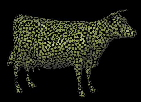
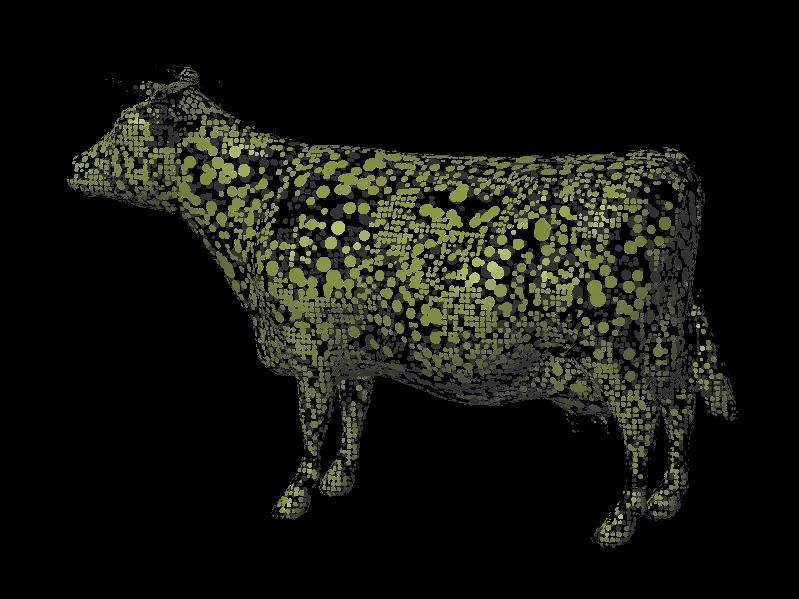
Since I was unable to find any surface splat models online, I attempted to generate my own to get things going. To get a (very bad) approximation of a surface splat model, I took a polygonal mesh and created a splat for each vertex in the mesh, using the vertex normal as the splat normal. For the radius of the splat, I took the distance to the farthest vertex of all triangles the splats parent vertex is part of. As can be seen below, the result is a poorly sampled model with certain splats grossly over-proportioned. It is however sufficient for testing the renderer.
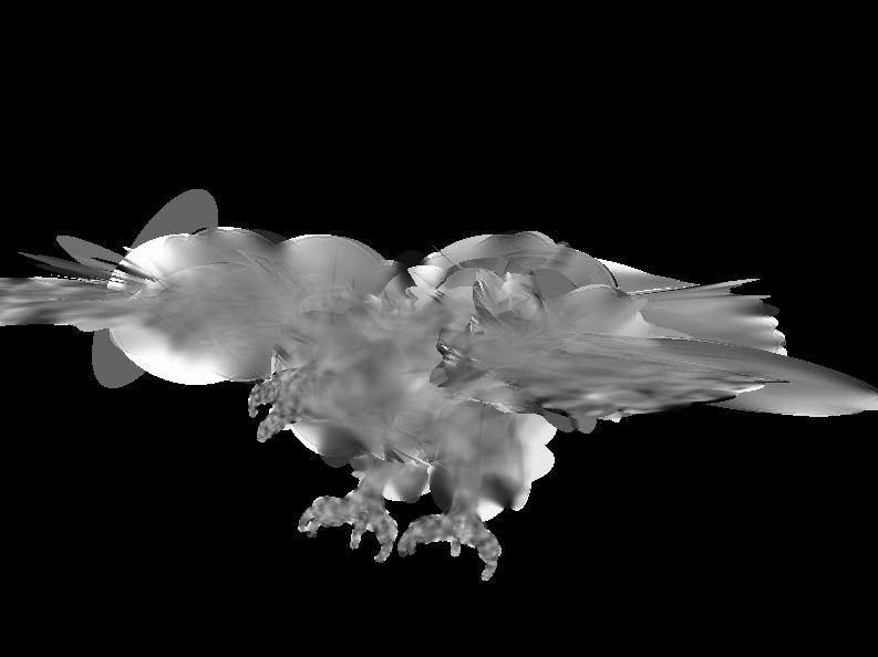
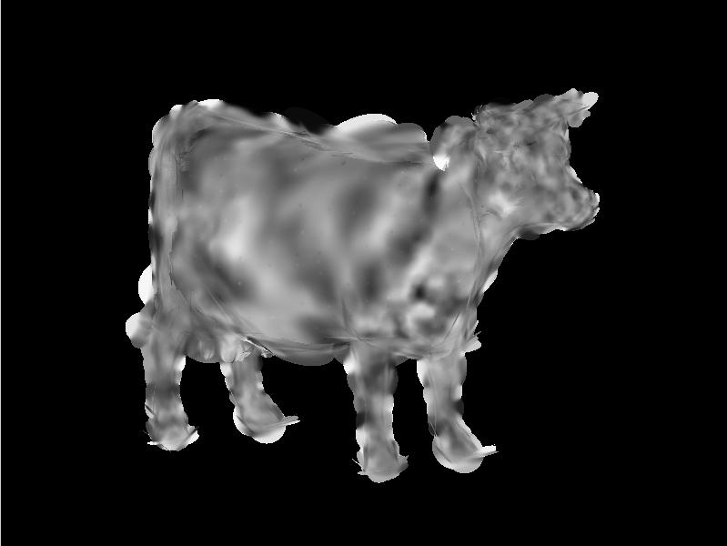
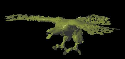
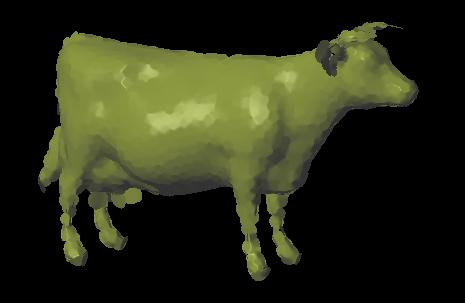
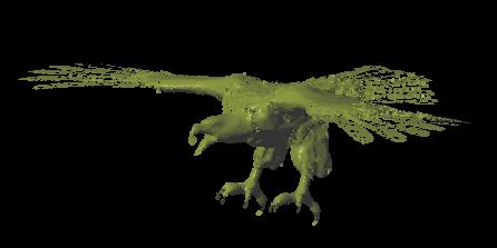
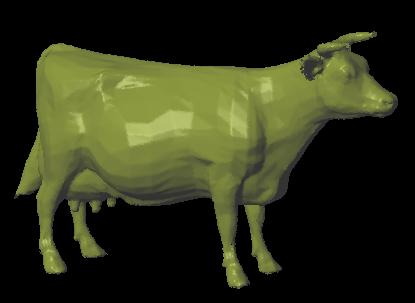
The following two images are of an eagle and cow model rendered using the surface splatting algorithm described above. At this time no shading calculations are performed. Each splat was assigned a random grayscale color value.
|
|
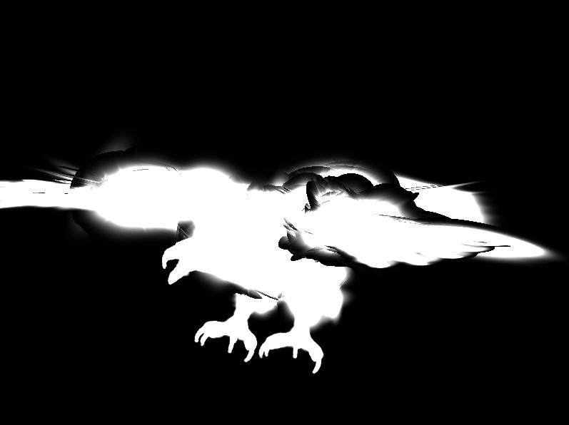
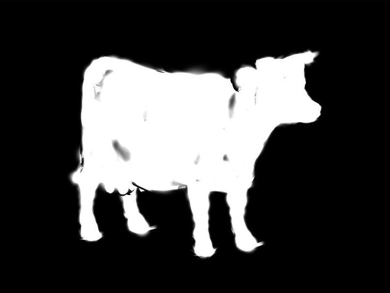
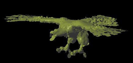
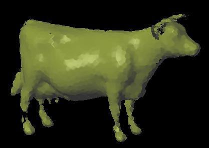
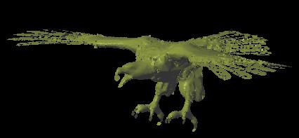
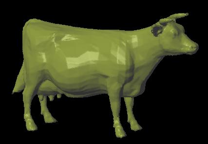
The next two images show are the same as the two above, except that the color at each pixel has not been normalized by dividing by the accumulated weight. The high dynamic range of the results is due to the use of 16-bit floating point render targets.
|
|
Using the Multiple Render Target (MRT) functionality of the latest graphics cards, it is possible to output both blended color and normals for each rendered pixel in pass two. The two images below show normal textures with normal values (x,y,z) interpreted as (r,g,b) values.
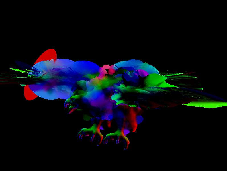
|
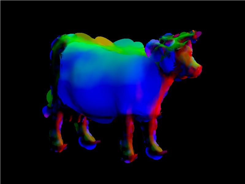
|
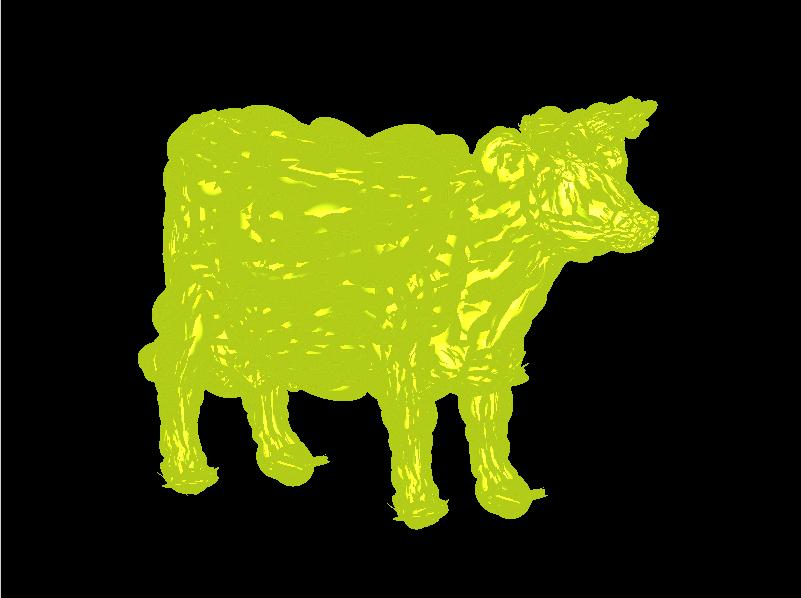
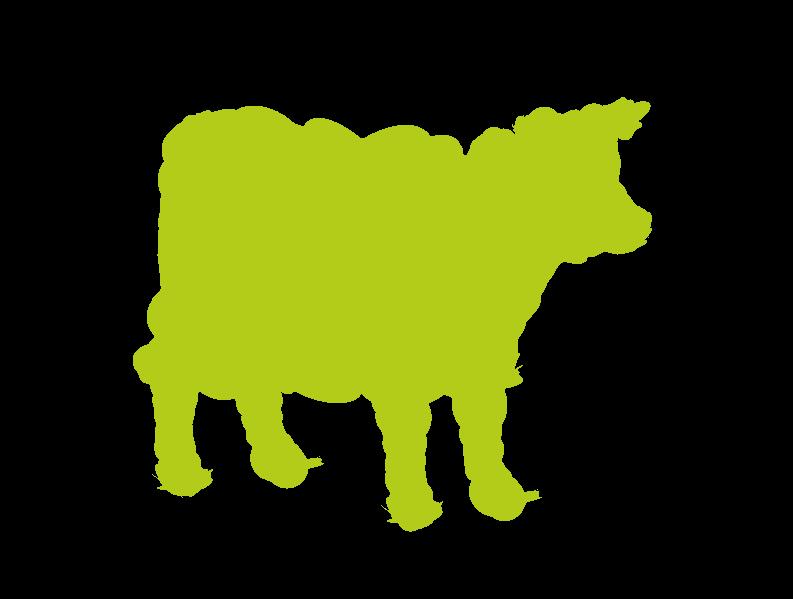
Due to the division in the normalization step, the use of 8-bit color channels can lead to visible artifacts due lack of precision. The following two images of a solid color cow model were rendered without any shading calculations. The image on the left was generated using 8-bits of precision for rendering and the image on the right using 16-bits of floating-point precision. The bright spots in the image on the left are due to numerical inaccuracies - the result of division by a very small number.
|
|
3. Update to Plan of Work
Due to unavailability of surface splat models, I will have to create my own. I plan to do this by taking a dense point set (possibly obtained by sampling a polygonal mesh) and use the algorithm described in [7] to turn the point set into an optimized set of circular surface splats. The following are updated goals for the next to project milestones:
Goals accomplished by April 15:
-Point-based renderer of circular surface splats completed.
-Algorithm for computing an optimized set of circular surface splats from a dense point set completed.
Goals accomplished by May 10:
-Investigation of how to add projective texturing to the surface splatting pipeline.
-Depending on time, incorporate the renderer into the tiled display system of the WAV project and observe results.
Project Update 2
As of this project update, I have completed a method of sampling a triangulated surface mesh into a set of circular surface splats. I have also finished the point-based renderer.
1. Mesh Sampling
In order to get some splat-based models to test my renderer, I implemented a partial implementation of the technique in [7] for sub-sampling a point cloud into a set of surface splats. To generate the point cloud, I wrote some code to sample a triangulated surface mesh along uniformly spaced rays parallel to a coordinate axis for all three coordinate axes, generating a point sample at each ray-mesh intersection. Prior to the sampling, the meshes were scaled to fit in a 2-cube centered around the origin.
Both the cow and eagle model from the last update were sampled at resolutions of 128x128 and 256x256 rays per coordinate axis. With each point sample I also stored an interpolated normal direction from the mesh at the location of the point sample for use in the sub-sampling algorithm.
I then wrote Matlab code to take the point cloud and sub-sample it into a set of circular surface splats with a given global error tolerance. To begin with, a splat is created for each point sample. The normal for the splat is created by taking the normal of a least-squares plane fit to the k nearest neighbors of the parent point. The generated normal is then compared to the normal from the mesh and is reversed if it points in a direction inconsisten with the interpolated normal taken from the mesh i.e. the dot product is negative. This ensures that all splat normals point outwards from the surface and not inwards.
Once the normal for each splat has been computed, a radius for the splat is required. The radius of the splat is found by considering the k nearest neighbors to each splat's parent point in the order of their 2D distance from the center of the splat when projected onto the plane of the splat. The neighbors are incorporated into the splat until the user specified error threshold is reached, which occurs when the distance along the normal of the splat to the included points is greater than the error tolerance. The radius is then set as the distance in the plane of the splat to the furthest included neighbor.
The current set of splats can now be used to render the surface, but it contains many overlapping and redudant splats. To greatly reduce the number of splats, a greedy selection method is employed which selects splats in the order of their surface area contribution until all sample points are covered. The results of the sub-sampling method are depicted below.
2. Shading Render Pass
Also as part of this update, I have completed the point-based renderer. In the last update I had completed passes one and two of the renderer and with this update, pass three has also been completed. After pass two, two textures which hold the material properties and normals of the object at each pixel have been created. In the shading pass, it is then possible to use the normals in conjunction with the material properties and information about the light source to perform per pixel shading. As mentioned in the previous update, the object material properties and normals must first be normalized by dividing their values by the accumulated weights of each kernel at the current pixel.
3. Results
Here are some images I was able to generate using the point-based renderer and models obtained by sub-sampling surface meshes of the cow and eagle from the previous update.
These first images are of the cow and eagle sampled into a point cloud using 128x128 rays per coordinate axis. For both models, the point cloud was sub-sampled into surface splats while enforcing an error tolerance of 2.4% of the bounding box diagonal - both models were prescaled to fit in a 2-cube before sampling.
|
|
| Eagle model - 24066 points reduced to 8657 splats. | Cow model - 24066 points reduced to 2238 splats. |
|
|
| Eagle model - 24066 points reduced to 8782 splats. | Cow model - 24066 points reduced to 2278 splats. |
There are some obvious problems with the models. There are holes in the legs of the cow, and some splats in the eagle model appear out of place, especially on the talons. The point clouds used to generate these models were sparsely sampled to begin with and a denser sampling should alleviate both problems to some extent. For the out of place splats on the eagle talon, a more optimal distribution of splats could help as well. The algorithm used to generate the models uses a greedy selection of splats that minimally covers the model and does not ensure a good distribution of splats.
The cow and eagle models were also sampled using 256x256 rays per coordinate axis. The following image show the results of the sub-sampling method on the generated point clouds. The models generated with an error tolerance of 2.4% of the bounding box diagonal are displayed first followed by the models generated using a tolerance of 0.24%.
|
|
| Eagle model - 94015 points reduced to 34480 splats. | Cow model - 93414 points reduced to 40913 splats. |
|
|
| Eagle model - 94015 points reduced to 34481 splats. | Cow model - 93414 points reduced to 40911 splats. |
The models generated using the denser initial sampling are of much better quality than the previous ones. The rendering of the cow model actually appears to have triangles even though it is composed completely of splats due to the fact that the point samples were generated from a triangle based surface mesh. The following image reduces the size of the splats so that the model is no longer closed and shows that the model is indeed composed of circular surface splats.
|
|
Final Update
Since the last update I have experimented with using the sub-sampling algorithm I implemented for the last project update to turn a set of point-cloud data representing a display surface in a
multi-projector display into a set of circular surface splats. I was also successful in adding projective texturing to the surface splat rendering pipeline. With these two goals accomplished,
it is possible to use the generated surface splat model to perform geometric image correction in a multi-projector display.
1. Display Surface Generation
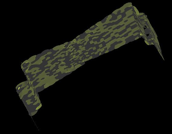
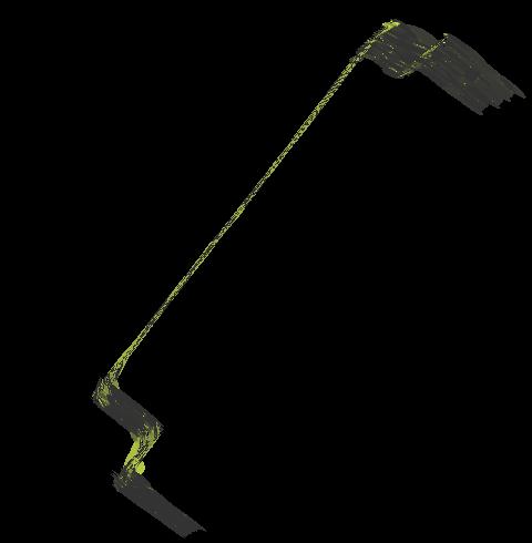
As part of the calibration process in the WAV project, we produce a point-cloud estimate of the display surface geometry. I ran one of the point-clouds generated in this way through the sub-sampler I implemented for Project Update 2 to produce a circular surface splat representation. The room geometry used consisted of two complex room corners. The images below show the point-cloud obtained during calibration and the resulting surface splat model. The model appears blotched due to inconsistent normal directions used in lighting. This inconsistency results from the ambiguity during sub-sampling as to which side of the least-squares plane the splat normal should lie. This will not affect image correction in a multi-projector display environment however since lighting is not performed.
As with the models from the previous update, this model suffers from a few holes. This is due to the sampling density used to generate the point-cloud relative to the global error tolerance used. Some splats also extend over the corners of the model, which can lead to visible artifacts when the model is used to perform image correction. This could be remedied by clipping splats which lie on the corner, forcing them to have a hard boundary.
|
|
|
|
2. Projective Texturing
In the WAV project, we use a projective texturing approach to correct for the image distortions that occur when projectors project onto display surfaces more complex than a simple plane. If a surface splat display model is to be used for image correction, some method of adding projective texturing to the rendering pipeling is needed. To accomplish this, I incorporated a projective texturing step into the attribute pass of the renderer. Since the attribute pass already computes a point in eye space for each pixel in the screen-space extent of each splat, I added a step to also invert the viewing transform to produce a point in world space. This point is then multiplied by the projection matrix representing the projector to produce a texture coordinate in the texture being projected. The texture is then sampled and the resulting color is accumulated in the material properties texture of the attribute pass, replacing the color of the splat.
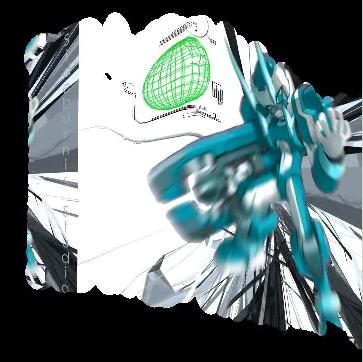
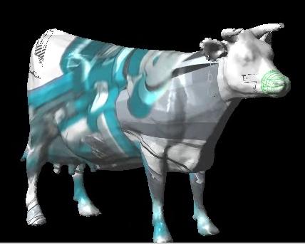
The following two images show the results of projective texturing. The first image is a texture being projected into one of the complex corners of the display surface model shown above. Note how the image "wraps" around the corner and is distorted. The texture has also been projected onto the cow model in the second image.
|
|
I also created a couple videos which show the texture moving on the model as it is translated back and forth while the projector remains static.
Display Surface Video | Cow Video
3. Conclusions
Over the course of this project I learned a lot about an alternate form of representing surfaces - surface splats. Surface splats have the same linear surface approximation order as a triangle mesh, but lack connectivity among primitives. This is advantageous in that each primitive is independent of the others, which may simplify changes to the geometry of the surface if it is being continuously estimated. Lack of connectivity can also be a disadvantage when it comes to determining which splats neighbor a certain splat. I found that point-based models also suffer from many of the same problems as triangulated surface meshes. It is not uncommon for surfaces to contain holes or blur sharp surface features due to undersampling.
I was successful in taking a point-cloud representation of a display model and converting it into a circular surface splat representation. I also showed it was possible to incorporate projective texturing into the surface splat rendering pipeline, which will allow the point-based model to be used in a multi-projector display to perform image correction in real-time. As future work, I plan to experiment with point-based representations for performing updates to surface geometry as it is continuously estimated.